1 - Node Expansion for 16G
Introduction
This document will guide users through how to add one or more scale unit nodes to their Dell Integrated System for Microsoft Azure Stack Hub that is fully installed and operational.
For the official Microsoft documentation on node expansion, see Add scale unit nodes - Azure Stack Hub.
Solution overview
The only way to increase the capacity of an Azure Stack Hub integrated system is to add more physical computers to the existing scale unit. The scale unit is a collection of physical computers that work together to provide compute, storage, and networking resources. Each physical computer in the scale unit is referred to as a scale unit node.
In order to add a scale unit node, you will need to physically rack, stack, and cable the new node(s), configure Top-of-Rack (ToR) switches, ensure firmware and BIOS configuration match the existing nodes, and add the new node(s) to the Azure Stack Hub integrated system via the Azure Stack Hub administrator portal. This document will guide you through this process.
NOTE
A single scale unit can support up to 16 nodes. You can add scale unit nodes to a scale unit until it reaches its maximum capacity.Audience
This node expansion guide is for Azure Stack Hub 16th-generation (16G) operators and the Dell Customer Service team who intend to add scale unit nodes to an existing Azure Stack Hub integrated system.
End-to-end deployment workflow
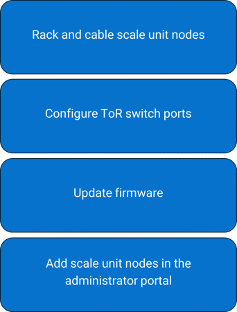
Node expansion workflow
Prerequisites
Ensure the following before you can add a node:
- Administrator access to the Azure Stack Hub integrated system.
- The rack and the power distribution unit (PDU) must be able to accommodate the new nodes.
- New scale unit (SU) nodes must use the same hardware configuration as the existing Azure Stack Hub scale unit nodes.
- The Azure Stack Hub integrated system must have the most current Microsoft and Dell Technologies patches and updates. If it does not, update it with the most recent patches and update versions before starting the node expansion process.
- The Azure Stack Hub integrated system must be healthy. Check the health state by logging in to the Azure Stack Hub administrator portal. Any active health alerts must be resolved before adding a scale unit node.
Rack, stack, and cable physical nodes
After the new scale unit node or nodes arrive at the customer site, on-site engineers must perform the manual process to rack, stack, and cable the new node(s).
Refer to the following diagrams for Top-of-Rack (ToR) switches cabling guidance.
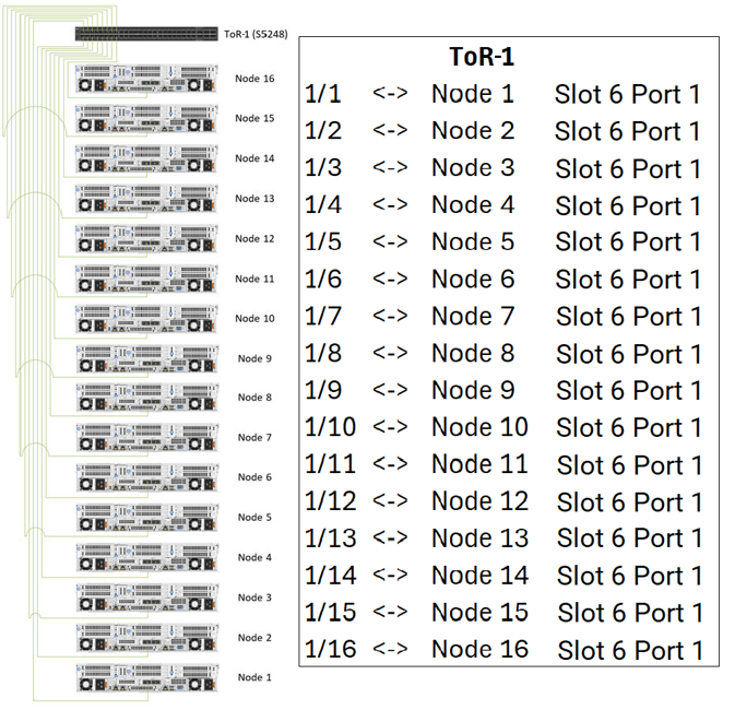
Scale unit node to ToR-1 network cabling
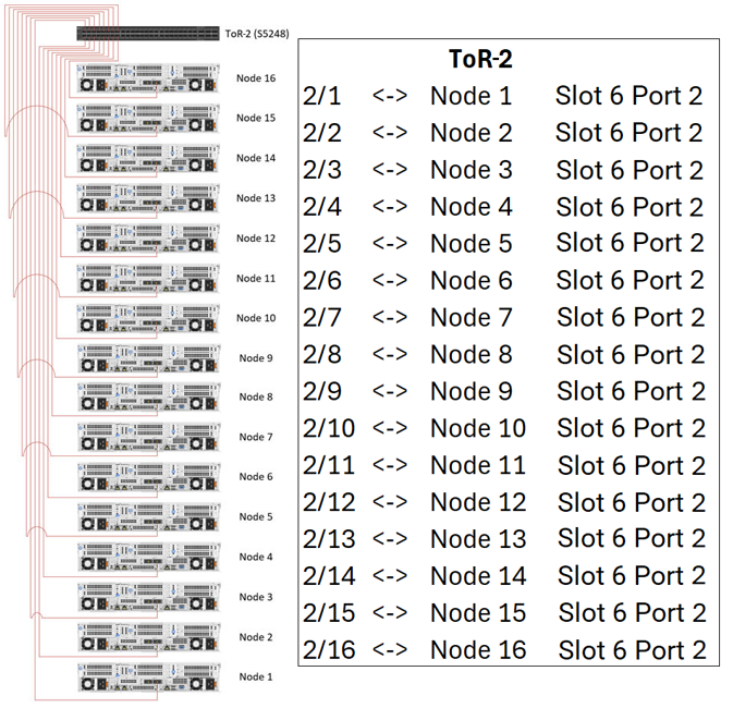
Scale unit node to ToR-2 network cabling
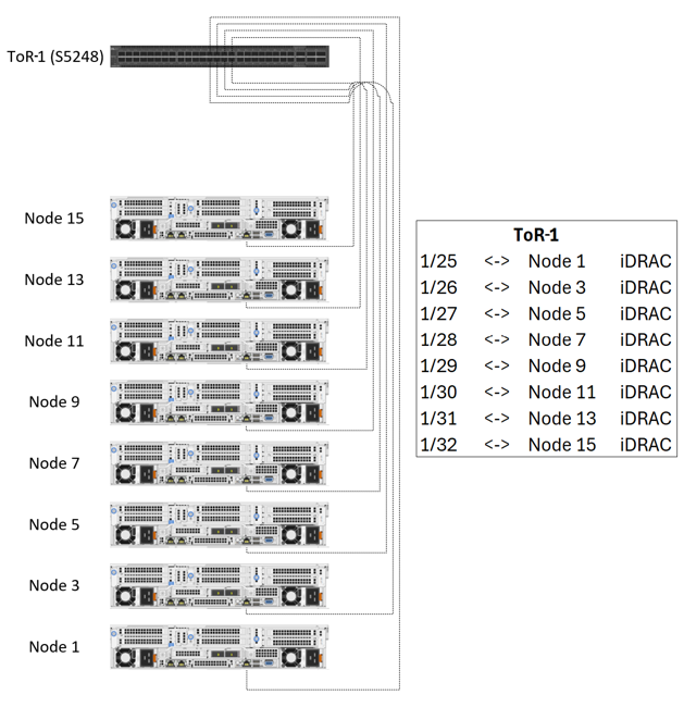
Scale unit node to ToR-1 iDRAC cabling
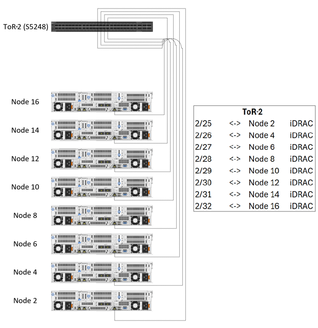
Scale unit node to ToR-2 iDRAC cabling
Check Component Readiness
After the new scale unit node or nodes are racked and cabled, power on the new node or nodes and check the LED indicator lights to ensure that all power supply and network cables are connected. See steps below on checking power readiness and checking network fabric connectivity before proceeding with a scale unit node expansion.
Check Power Readiness
To check power readiness, perform the following steps:
Steps
- Use a separate power bus for each power distribution unit (PDU).
- Ensure that the PDUs are firmly connected to the applicable power sources.
- Ensure that the PDUs are powered on.
- All servers and switches are equipped with dual power supplies. Ensure that these power supplies are connected to separate PDUs to ensure power redundancy.
Checking network fabric connectivity
Ensure that the new and existing scale unit nodes are connected to the ToR switches.
- The odd numbered nodes iDRAC (OoB) port connects to the ToR-1 switch.
- The even numbered nodes iDRAC (OoB) port connects to the ToR-2 switch.
- The Slot 6 Port 1 port is connected to the ToR-1 switch.
- The Slot 6 Port 2 port is connected to the ToR-2 switch.
The following figure shows the port locations for an AS-760 server.
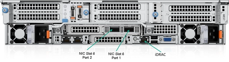
Port Locations for AS-760
S5248F-ON ToR-1 port map
The following table lists the Slot 6 Port 1 connections, cable types, node ports, and switch ports to the S5248F-ON ToR-1 switch.
| Origin | Destination | Cable Type |
|---|---|---|
| ToR-1 Port 1 | Slot 6 Port 1 on Node 1 (AS-760) | 25 GbE Twinax |
| ToR-1 Port 2 | Slot 6 Port 1 on Node 2 (AS-760) | 25 GbE Twinax |
| ToR-1 Port 3 | Slot 6 Port 1 on Node 3 (AS-760) | 25 GbE Twinax |
| ToR-1 Port 4 | Slot 6 Port 1 on Node 4 (AS-760) | 25 GbE Twinax |
| ToR-1 Port 5 | Slot 6 Port 1 on Node 5 (AS-760) | 25 GbE Twinax |
| ToR-1 Port 6 | Slot 6 Port 1 on Node 6 (AS-760) | 25 GbE Twinax |
| ToR-1 Port 7 | Slot 6 Port 1 on Node 7 (AS-760) | 25 GbE Twinax |
| ToR-1 Port 8 | Slot 6 Port 1 on Node 8 (AS-760) | 25 GbE Twinax |
| ToR-1 Port 9 | Slot 6 Port 1 on Node 9 (AS-760) | 25 GbE Twinax |
| ToR-1 Port 10 | Slot 6 Port 1 on Node 10 (AS-760) | 25 GbE Twinax |
| ToR-1 Port 11 | Slot 6 Port 1 on Node 11 (AS-760) | 25 GbE Twinax |
| ToR-1 Port 12 | Slot 6 Port 1 on Node 12 (AS-760) | 25 GbE Twinax |
| ToR-1 Port 13 | Slot 6 Port 1 on Node 13 (AS-760) | 25 GbE Twinax |
| ToR-1 Port 14 | Slot 6 Port 1 on Node 14 (AS-760) | 25 GbE Twinax |
| ToR-1 Port 15 | Slot 6 Port 1 on Node 15 (AS-760) | 25 GbE Twinax |
| ToR-1 Port 16 | Slot 6 Port 1 on Node 16 (AS-760) | 25 GbE Twinax |
The following table lists the iDRAC connections, cable types, node ports, and switch ports to the S5248F-ON ToR-1 switch.
| Origin | Destination | Cable Type |
|---|---|---|
| ToR-1 Port 25 | iDRAC on Node 1 (AS-760) | 1GbE Cat-6 |
| ToR-1 Port 26 | iDRAC on Node 3 (AS-760) | 1GbE Cat-6 |
| ToR-1 Port 27 | iDRAC on Node 5 (AS-760) | 1GbE Cat-6 |
| ToR-1 Port 28 | iDRAC on Node 7 (AS-760) | 1GbE Cat-6 |
| ToR-1 Port 29 | iDRAC on Node 9 (AS-760) | 1GbE Cat-6 |
| ToR-1 Port 30 | iDRAC on Node 11 (AS-760) | 1GbE Cat-6 |
| ToR-1 Port 31 | iDRAC on Node 13 (AS-760) | 1GbE Cat-6 |
| ToR-1 Port 32 | iDRAC on Node 15 (AS-760) | 1GbE Cat-6 |
S5248F-ON ToR-2 port map
The following table lists the Slot 6 Port 2 connections, cable types, node ports, and switch ports to the S5248F-ON ToR-2 switch.
| Origin | Destination | Cable Type |
|---|---|---|
| ToR-2 Port 1 | Slot 6 Port 2 on Node 1 (AS-760) | 25 GbE Twinax |
| ToR-2 Port 2 | Slot 6 Port 2 on Node 2 (AS-760) | 25 GbE Twinax |
| ToR-2 Port 3 | Slot 6 Port 2 on Node 3 (AS-760) | 25 GbE Twinax |
| ToR-2 Port 4 | Slot 6 Port 2 on Node 4 (AS-760) | 25 GbE Twinax |
| ToR-2 Port 5 | Slot 6 Port 2 on Node 5 (AS-760) | 25 GbE Twinax |
| ToR-2 Port 6 | Slot 6 Port 2 on Node 6 (AS-760) | 25 GbE Twinax |
| ToR-2 Port 7 | Slot 6 Port 2 on Node 7 (AS-760) | 25 GbE Twinax |
| ToR-2 Port 8 | Slot 6 Port 2 on Node 8 (AS-760) | 25 GbE Twinax |
| ToR-2 Port 9 | Slot 6 Port 2 on Node 9 (AS-760) | 25 GbE Twinax |
| ToR-2 Port 10 | Slot 6 Port 2 on Node 10 (AS-760) | 25 GbE Twinax |
| ToR-2 Port 11 | Slot 6 Port 2 on Node 11 (AS-760) | 25 GbE Twinax |
| ToR-2 Port 12 | Slot 6 Port 2 on Node 12 (AS-760) | 25 GbE Twinax |
| ToR-2 Port 13 | Slot 6 Port 2 on Node 13 (AS-760) | 25 GbE Twinax |
| ToR-2 Port 14 | Slot 6 Port 2 on Node 14 (AS-760) | 25 GbE Twinax |
| ToR-2 Port 15 | Slot 6 Port 2 on Node 15 (AS-760) | 25 GbE Twinax |
| ToR-2 Port 16 | Slot 6 Port 2 on Node 16 (AS-760) | 25 GbE Twinax |
The following table lists the iDRAC connections, cable types, node ports, and switch ports to the S5248F-ON ToR-2 switch.
| Origin | Destination | Cable Type |
|---|---|---|
| ToR-2 Port 25 | iDRAC on Node 2 (AS-760) | 1GbE Cat-6 |
| ToR-2 Port 26 | iDRAC on Node 4 (AS-760) | 1GbE Cat-6 |
| ToR-2 Port 27 | iDRAC on Node 6 (AS-760) | 1GbE Cat-6 |
| ToR-2 Port 28 | iDRAC on Node 8 (AS-760) | 1GbE Cat-6 |
| ToR-2 Port 29 | iDRAC on Node 10 (AS-760) | 1GbE Cat-6 |
| ToR-2 Port 30 | iDRAC on Node 12 (AS-760) | 1GbE Cat-6 |
| ToR-2 Port 31 | iDRAC on Node 14 (AS-760) | 1GbE Cat-6 |
| ToR-2 Port 32 | iDRAC on Node 16 (AS-760) | 1GbE Cat-6 |
Configure ToR Switches
Using a crash cart with a serial connection or an SSH connection to the ToR switches, ensure that all ports that have a new node connected have been configured correctly.
To configure the ToR switches, perform the following steps:
Steps
-
Log in to the S5248F-ON ToR-1 switch
-
Once logged in type the commands below to configure the data link connections to the newly added scale unit nodes. For example, if wishing to expand a four-node scale unit with additional four nodes, you would run the below on the switch:
conf t interface range ethernet 1/1/5-1/1/8 description "CL01 Nodes NIC" no shutdown switchport mode trunk switchport access vlan 7 switchport trunk allowed vlan 107 mtu 9216 flowcontrol receive off priority-flow-control mode on service-policy input type network-qos AZS_SERVICES_pfc service-policy output type queuing AZS_SERVICES_ets ets mode on qos-map traffic-class AZS_SERVICES_Que spanning-tree bpduguard enable spanning-tree guard root spanning-tree port type edge exit -
Once the data link port or ports are configured on the switch proceed to configuring the BMC Management ports. For example, if wishing to expand a four-node scale unit with an additional four nodes, you would run the below on the switch:
conf t interface range ethernet 1/1/27:1-1/1/28:1 description "BMCMgmt Ports" no shutdown switchport access vlan 125 mtu 9216 flowcontrol receive off spanning-tree bpduguard enable spanning-tree guard root end -
Once the BMC Management port or ports have been configured you will need to run the command below to write the new configuration into memory on the switch:
copy running-configuration startup-configuration -
Once you have completed steps 1-4, repeat them on the ToR-2 switch.
Accessing the iDRAC Direct port
The iDRAC Direct port is a USB port located on the front of the server and is used to access the iDRAC web interface, RACADM, and Redfish API, without needing to connect to the network.
NOTE
The factory default defined iDRAC administrator credential username will be azsinstall and the password will be azsinstall. This credential will be rotated as part of the node expansion process.To access the iDRAC Direct port, perform the following steps:
Steps
- To access the iDRAC Direct port, you must connect a USB Type A to micro-USB cable from a laptop or mobile KVM host to the micro-USB port on the front of the server.
- From your host, turn off any wireless networks and disconnect from any other hard-wired networks.
- Connect a USB Type A to micro-USB cable from your host to the iDRAC Direct micro-USB port located on the front control panel of the AS-760 server.
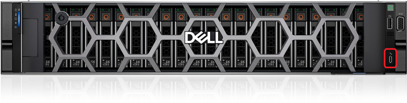
AS-760 front view with iDRAC Direct port highlighted
- Wait for the host to acquire an IP address of 169.254.0.4. It may take several seconds for the IP address to be acquired. The iDRAC will acquire an IP address of 169.254.0.3.
- Open a web browser and provide the iDRAC Direct port IP address as the URL. For example, https://169.254.0.3.
- At the certificate warning window, click Advanced and then click Proceed to 169.254.0.3 (unsafe).
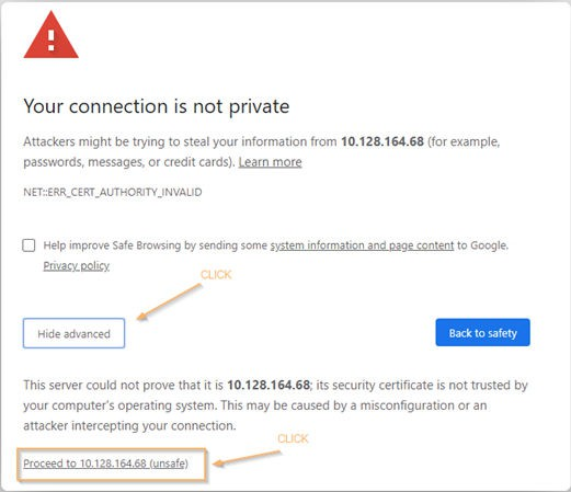
Certificate warning window
- Enter the factory default username and password for the iDRAC, and click Log In.
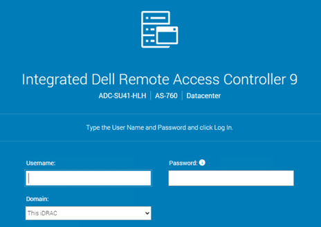
iDRAC 9 login screen
Assigning iDRAC IP addresses to the new scale unit nodes for expansion
The iDRAC IP address assignment is a manual step. The iDRAC Direct port can be leveraged on the node(s) to assign the iDRAC IP addresses based on the assigned BMC management (BMCMgmt) network IP address from the Azure Stack Hub deployment worksheet.
To manually assign the iDRAC IP addresses to the new scale unit nodes for expansion, perform the following steps:
Steps
The below steps will be repeated for each new scale unit node to be added.
- Follow the steps previously mentioned on Accessing the iDRAC Direct port.
- From the iDRAC dashboard, browse to iDRAC Settings > Connectivity and expand the Network > IPv4 Settings menu.
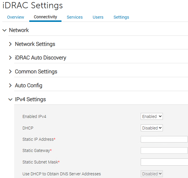
iDRAC Settings > Network > IPv4 Settings menu
- Set the static IP address, static gateway, and static subnet mask according to the values defined in the Azure Stack Hub deployment worksheet. These IP addresses are defined by the BMCMgmt /26 subnet provided to the deployment worksheet.
- For more information about the deployment worksheet for Azure Stack Hub integrated systems, please see: Deployment worksheet - Azure Stack Hub.
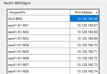
Azure Stack Hub deployment worksheet BMCMgmt network
- Click Apply.
Perform a health check on the new nodes
Prior to running the node expansion script, it is important to perform a quick health check of the new node(s). This also allows the iDRAC to perform an inventory collection which is needed for the firmware upgrade automation to successfully validate the new node(s).
To perform a health check on the new nodes for expansion, perform the following steps:
Steps
The below steps will be repeated for each new scale unit node to be added.
- If the new node(s) are powered off, press the power button to boot the new node(s).
- Allow up to 10 minutes for the new node(s) to fully load BIOS settings and complete the BIOS initialization.
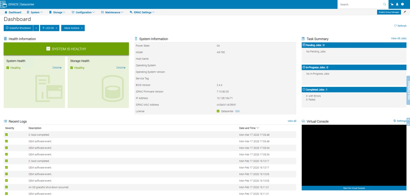
- Once complete, access the iDRAC web interface either via the iDRAC Direct port or by leveraging a remote desktop (RDP) connection from the Hardware Lifecycle Host (HLH).
- Verify there are no alerts or warnings on the dashboard.
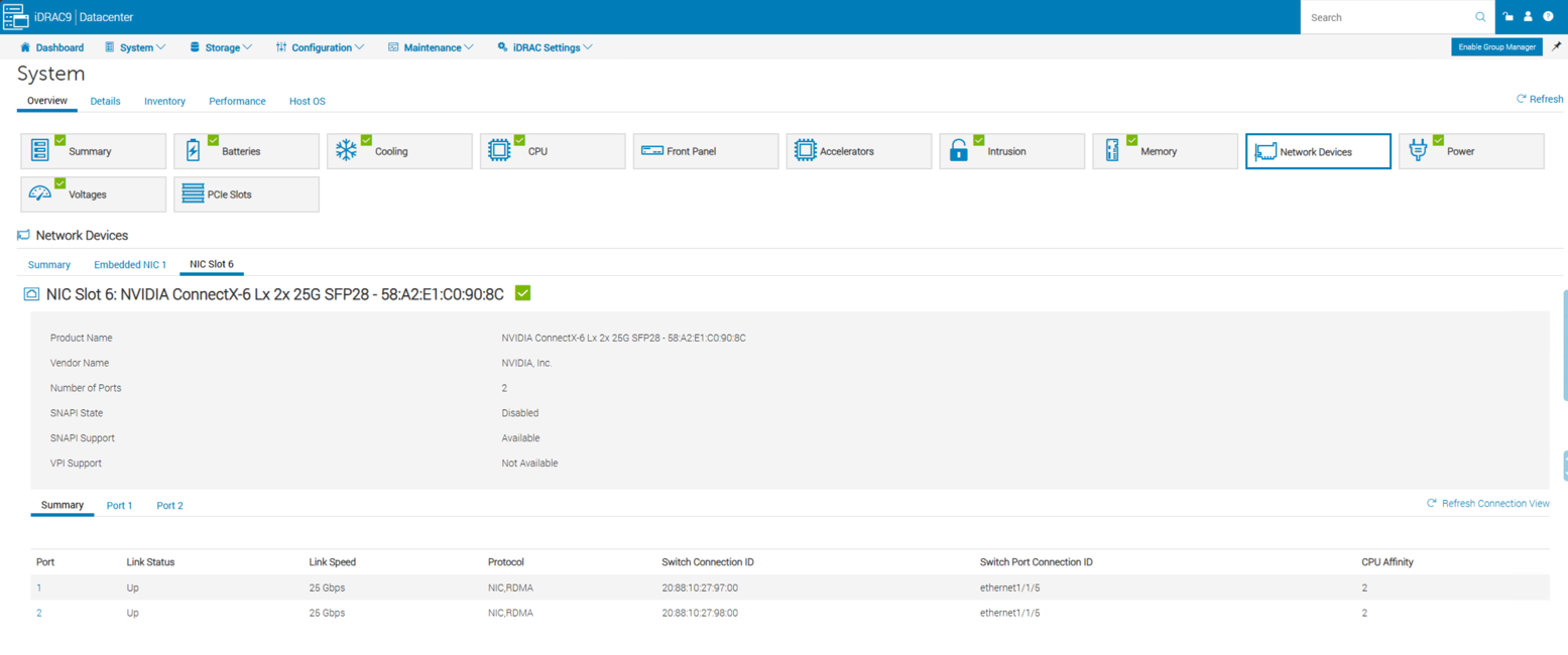
- Navigate to System > Overview > Network Devices and verify that NIC Slot 6 shows both ports with a Link Status of Up.
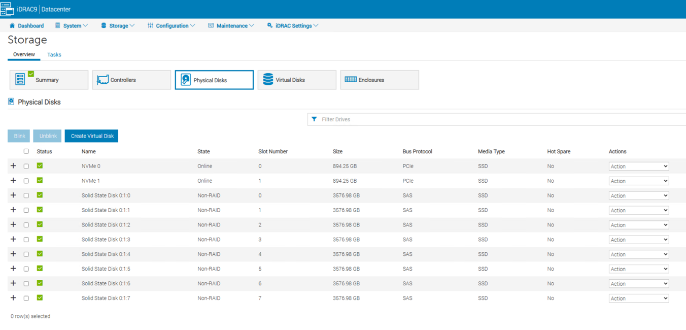
- Navigate to Storage > Overview > Physical Disks and verify all drives are present and healthy.
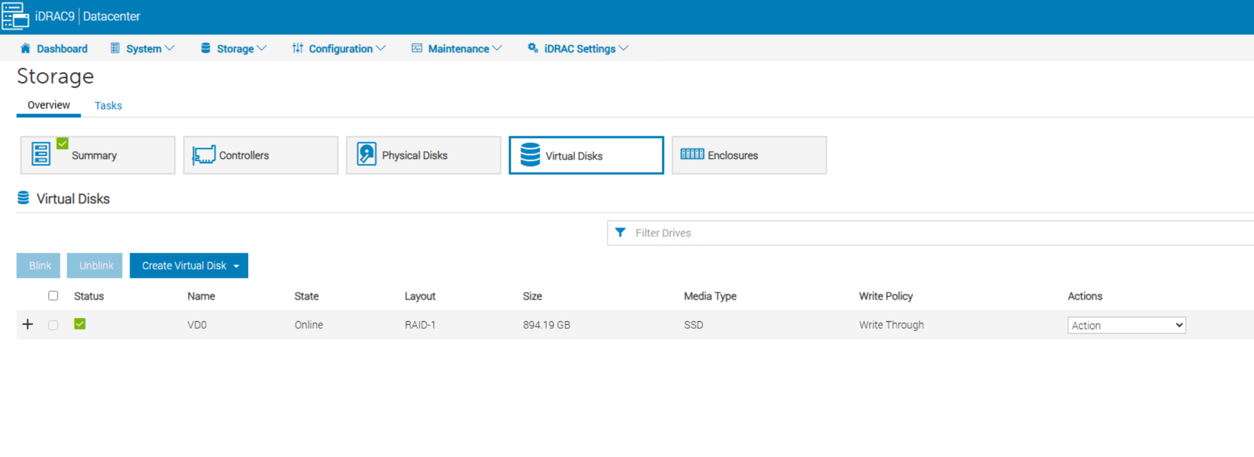
- Navigate to Storage > Overview > Virtual Disks and verify a virtual disk is present.
- Once complete, navigate back to the Dashboard and power off the node.
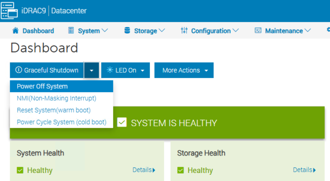
Update firmware on new scale unit nodes
This section covers updating firmware on scale unit node(s).
WARNING
To maintain the integrity of Dell Azure Stack Hub Integrated System before adding any new scale unit nodes, you must first follow the Patch and Update guide which includes Lifecycle Manager, ToR switch firmware updates, and OEM package updates.
This will ensure that any new scale unit nodes have the correct firmware and BIOS configuration applied when they are added to the cluster.
Node expansion script
The node expansion script is used to update firmware and apply BIOS configuration on the new scale unit node(s) before they are added to the Azure Stack Hub integrated system.
The script will also update the DeploymentData JSON file with the new scale unit node(s) information.
The script will not add the new scale unit node(s) to the Azure Stack Hub integrated system, see the Add scale unit node in the Azure Stack Hub administrator portal section for more information on how to add the new scale unit node(s) to the Azure Stack Hub integrated system.
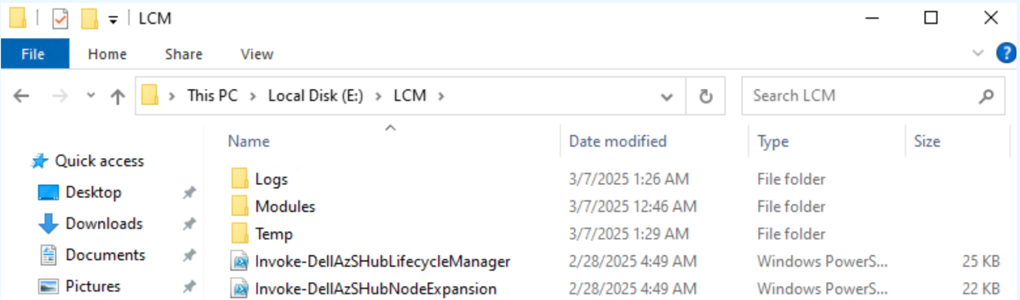
Dell Integrated System for Microsoft Azure Stack Hub Lifecycle Manager contains the node expansion script, Invoke-DellAzSHubNodeExpansion.ps1. After completing the Patch and Update process, you should have the latest Lifecycle Manager available in E:\LCM.
WARNING
Ensure that the new scale unit node(s) are powered off before running the Invoke-DellAzSHubNodeExpansion.ps1 script, otherwise the script will fail.NOTE
The factory default defined iDRAC administrator credential username is azsinstall and the password is azsinstall.To run the node expansion script, perform the following steps:
Steps
-
From the HLH, open a PowerShell console window as an administrator.
-
Before running the node expansion script, make sure you have the following information:
- Number of nodes being added
- Factory BMC user credentials
- BMC administrator credentials
- HLH administrator credentials
-
Change the directory to E:\LCM
Set-Location -Path E:\LCM -
Run the following command to start the expansion process. Change the “X” to the number of nodes that are being added.
.\Invoke-DellAzSHubNodeExpansion.ps1 -AdditionalNodeCount X -
You will be prompted to input the BMC user, BMC administrator and HLH administrator credentials before the upgrade begins.
The automation will run the firmware update process one node at a time. Each node will take about an hour to complete.
Once the firmware update process is complete on all nodes your prompt will look as shown below. The new nodes have now been added to the DeploymentData JSON file and are ready to be added to the cluster from the Azure Stack Hub administrator portal:
(...)
VERBOSE: 20250214-225038:Invoke-FirmwarePostUpdate:Invoke-OEMFirmwarePostUpdate completed successfully.
VERBOSE: 20250214-225038:Remove-AutoLogon:Removing auto admin logon.
VERBOSE: 20250214-225038:Resume-HLHBitLocker:Importing BitLocker module.
VERBOSE: 20250214-225038:Resume-HLHBitLocker:Getting BitLocker encrypted volumes.
VERBOSE: 20250214-225039:Resume-HLHBitLocker:Restoring TPM protector on volume 'D:'.
VERBOSE: 20250214-225039:Disable-DHCPServer:Disabling DHCP server service.
VERBOSE: 20250214-225039:Invoke-OEMFirmwareBootstrap:PROGRESS - Cleanup complete.
VERBOSE: 20250214-225039:Invoke-OEMFirmwareBootstrap:PROGRESS - Invoke-OEMFirmwareBootstrap completed successfully.
Finished running Invoke-FirmwareBootstrap for sac42-S1-N08 - 10.128.164.74 with Deployment Data JSON: E:\AzureStack\DeploymentData_new_one.json
  > List of nodes in the Deployment Data JSON: 'E:\AzureStack\DeploymentData_new_one.json'.

Name         BMCIPAddress
----         ------------
sac42-S1-N01 10.128.164.67
sac42-S1-N02 10.128.164.68
sac42-S1-N03 10.128.164.69
sac42-S1-N04 10.128.164.70
sac42-S1-N05 10.128.164.71
sac42-S1-N06 10.128.164.72
sac42-S1-N07 10.128.164.73
sac42-S1-N08 10.128.164.74

(...)

  > Successfully replaced the original Deployment Data JSON with the new one.
Locate Logs
To locate the logs from the node expansion script, perform the following steps:
Steps
-
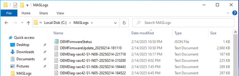
From the HLH, open File Explorer and navigate to the C:\MASLogs folder.
-
The logs that were generated from the node expansion script will have the filename: OEMFirmwareUpdate_[date]-[time].
Add scale unit node in the Azure Stack Hub administrator portal
The operation to add a scale unit node consists of two distinct phases: compute and storage.
The compute expansion process can take between 1-3 hours to complete per scale unit node. The storage expansion process can take several days to complete, depending on the size of the storage pool and the number of scale unit nodes being added.
NOTE
To perform any tasks within the Azure Stack Hub administrator portal, you must have the necessary administrator privileges to the Default Provider Subscription.Before adding a scale unit node within the Azure Stack Hub administrator portal, ensure that you have completed all the steps below:
- Rack, stack, and cable the physical node(s).
- Configure ToR switches.
- Update firmware on the new scale unit node(s).
WARNING
While an add scale unit node operation is already in progress do not attempt any of the following operations:
- Stop Azure Stack Hub
- Update Azure Stack Hub
- Repair/FRU scale unit node
- Certificates rotation
- Add another scale unit node (the previous add scale unit node operation failure is also considered in progress)
Steps
WARNING
Only one scale unit node can be added at a time during the compute expansion process. Once one scale unit node has been successfully added to the cluster, you can proceed with adding the next scale unit node.- Log into the Azure Stack Hub administrator portal as an Azure Stack Hub administrator.
- Browse to All services > Region management > Scale units > [Cluster name] > Nodes.
- Click the Add node button.
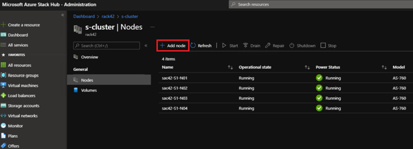
- The Region and the Scale unit will be populated automatically. You will need to specify the BMC IP Address of the scale unit node you are adding.
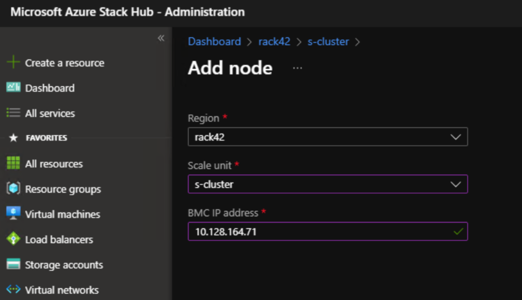
-
Once you have entered the IP address of the new scale unit node, click Add at the bottom of the screen.
NOTE
The add node operation first adds the new scale unit node as available compute capacity and then automatically extends the storage capacity.
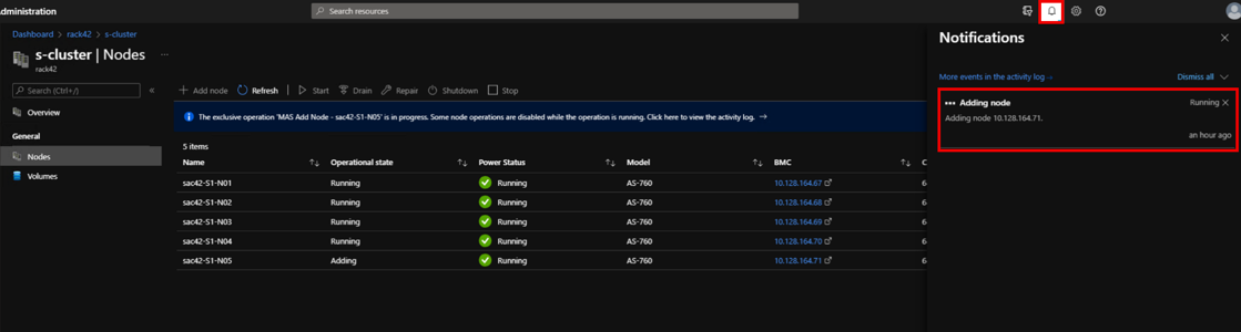
It will take a few minutes for the new scale unit node to be visible in the Azure Stack Hub administrator portal. The new scale unit node will be in a Adding state until the compute expansion process is complete.
-
Click the notifications in the upper right to check the status as shown below:
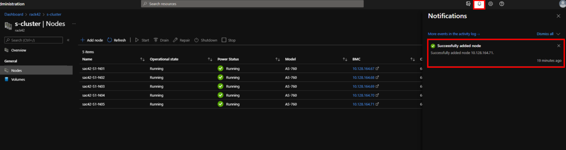
- Once the scale unit node expansion compute process is complete, your notifications will show as the following:
CAUTION
After a scale unit node is added, the storage expansion process begins and can run for multiple days before it completes the expansion.
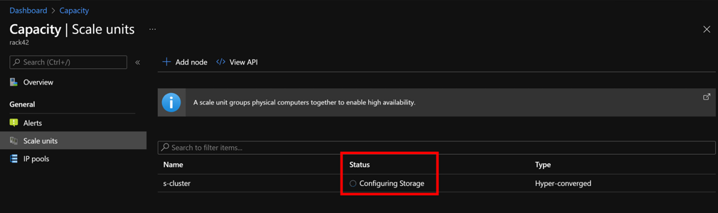
-
In order to check the status of the storage expansion provisioning task you can navigate to All services > Region management > Scale units. Once here, you will see the status as Configuring Storage if the storage expansion provisioning task is not yet complete. When this task is complete the status will change to Running.
NOTE
You do not need to wait for the Configuring Storage task to complete before adding the next scale unit node.
There is no impact to the running workloads while another scale unit node is being added.